Scenario details (assumptions)
An educational institution, loosely modelled after the university of Plymouth, requires a new datacentre to support operations. The datacentre is required to support administrative operations specifically. These operations include web, and file storage capabilities.
There are two types of employee in the administration. General Information (GI) which complete general tasks, and staff which handle Sensitive Information (SI) such as disability/health related documents.
A web site supporting GI employees, is required. This will hold the employee self-service system, responsible for expense claims, contractual information, payroll and holiday authorisation. SI employees will also have access to this system for their general needs. This includes an SQL backend, storing data, and receiving requests from web servers.
A file server for SI employees to store supporting
documents, is also needed, and required to be secure.
Estimates
Peak usage
To estimate usage, it is assumed that there are five departments, with fifteen staff each. Twenty percent of which are SI staff. For a total of seventy-five, of which fifteen access SI resources.
To estimate GI services, the Moodle website will be used. On initial load the main page transfer takes 2.5MB. Subsequent loads transfer 1017kb. The load comes from GI staff using the services to perform their duties. It is assumed that a GI staff member will request 80 pages per hour. At seventy-five staff this comes to a peak of, 6000 per hour, 100 requests per minute, or roughly 0.816 Gigabits of throughput.
SI services require file transfer. After the GI requests there is 23MBs of headroom for file transfer. It is assumed that Si staff behaviour, is to upload files to the SI file server for filing and storage, after sensitive paperwork has been submitted. The processing of paperwork by SI staff is for one file per 20 minutes. Assuming a file size of 1.2MB, at fifteen SI staff, this equates to 54MB per hour. Which is less than 1MBs average. With TCP Windowing, file transfer will exceed this speed briefly but should not reach 23MBs, even with fifteen users.
Light use on main SI server, allows for its resources to be timeshared with the GI server. Migration of VM’s from the high load of the SE server to the SI server, will maintain a high degree of reliability and speed for the datacentre as a whole.
Hardware
Cabling
The traffic estimation concludes that standard gigabit cabling is sufficient to handle client requests to and from the GI services. As well as file transfers for SI staff. Each server will need at minimum two Gigabit Lan ports, and a lower speed 100/100 port. The GI VLan requires ~0.8 Gigabits of throughput. The management VLan requires Gigabit throughput for after hours backups. And the SI VLan does not need much throughput.
Storage
The storage requirements come from the SI file storage server. At 23,000 students and an estimated incidence of disability between 0.8 and 5.7 (The Office for Disability Issues, n.d.), I estimate the percentage of university students to be near two percent. This gives an estimated number of students with SI files of 460. At minimum the storage requirements would be 8GB. This includes medical documentation, as well as extenuating circumstances for four years.
Each apache VM for processing web requests will take up 10GB for web resources.
The SQL server will take up more space than the Apache VM’s, and is a singular server instance holding the data for the GI service. 100Gb will be provisioned for this VM.
The load balancing VM’s storage will be minimal at 3GB as this mainly requires processing.
In total, a minimum of 132GB. With two apache VM’s. This storage will reside on a shared SAN.
Processing
Both servers will be hardware identical to allow for failover I the event of hardware failure. This means that each server needs to handle the requests for the entirety of the GI and SI services if the need arises.
This will require each Server to have a threading capacity of at least 9 threads. Three for load balancing, and web VMs. And three each for the file, and SQL VMs.
RAM
1GB for each load balancing, and web VM, at least three. 2GB for the SQL server, to ensure efficient processing of requests. 2GB for the File server. A total of 7GB.
Implementation
Security
Security in the design is provided by the segmentation in place. The VLan’s limit the ability for potential vulnerabilities to be leveraged. In the event an attacker is able to access a VM. They will only be able to attack other areas of their respective VLan.
The management VLan is only available through physical access. No forwarding is done by the router, and internet access is monitored by an IDS. The GI VLan is accessed through the router by port forwarding ports 80 and 443, for HTTP and HTTPS respectively. This allows GI users to easily access the GI site. As the site is not forwarded to the internet, it will not be targeted by automated scans.
Hardware
Disks
Direct attached storage will be used for each server. Each server’s disks are part of a five disk RAID array configured in RAID 5. This gives a storage efficiency of 80 percent. Each disk will store 250GB, meaning a total array, per server, of 931GB after efficiency.
This RAID implementation will allow high performance, as write and read operations can overlap. Write operations will require the recalculation of the parity information, but this write operation will occur on a different disk from the origin write. So should not impact performance significantly. Disk failure is also mitigated through the distributed parity information. The array will still be able to function with one disk failure. However, a successive failure within this replacement window could cause the array to fail, especially with batch-correlated failures.
To mitigate batch-correlated failure from the use of disks from the same batch. It is recommended in this instance to diversify the origin of disks, in both manufacturer and production batch (Paris & Long, 2006). Disks will be procured from entirely different manufacturers and batches, used and evenly allocated to the SAN to maximise disk diversity. Spares from this process will be kept stored for the event of disk failure, to be immediately swapped for array rebuild. This would reduce the likelihood of batch-correlated failure from 63% to 0.02%, when replacing a failed disk within one day. The mean time between failures for the 5 disk array is near 320,000 hours using modern disks. Individually they are near 1.6 million.
This implementation is used in conjunction with a shared Storage Area Network (SAN). Where each server comprises a host with access to the entirety of the SAN.
Networking
Each server requires three ethernet ports. One for each VLan. Through these the VM’s will be only able to reach their respective users through the router, while the VM’s themselves will not have routing to other VLans.
Reliability
Reliability is maintained by the duplication of hardware. In the event that a physical server becomes inoperable, due to firmware/software upgrades, or damage. The VM’s can be manually temporarily migrated to the other, while normal operations are being restored.
Load Balancing
The load balancer VM is responsible for balancing the load of incoming https connections to the running apache web VM’s. A utility such as HAProxy running in the VM, allows this. Running the load balancer in a VM ensures uptime, as another instance can be configured quickly.
Load balancing in this way ensures that capacity can scale linearly. While this approach will incur a slight latency increase, this should be made up for in the increased throughput multiple server instances provide.
Virtualising the load balancing, and web servers in this way imparts important benefits. Outer-network communication is conserved for the serving of client data, and intra-network communication is received by the VM’s quickly. Not needing to go through a physical network switch, just to come back into the LAN, it is handled inside the hypervisor on a virtual switch. This allows the load balancer to communicate directly with each server to gather load data, and make informed balancing decisions.
The usage of ESXi however, means that further provisioning of extra resources to load balance, requires manual intervention. Unlike other cloud platforms which offer this as an automated service.
Software
Virtualisation has been chosen for this design, as to minimise the redundancy of hardware that comes with physically expanding a datacentre. Dedicated tasks running each on a physical host, does not utilise the full power of the hardware available. Virtualisation ensures the hardware runs at an efficient capacity, in terms of hardware, space, and power.
The management of these devices is achieved through the ESXi, bare-metal hypervisor. Rather than host based. Bare metal ensures the least amount of non-virtualisation overhead. Through the web client, ESXi command line, or various vSphere programs, the hypervisor can be configured to run VM’s as needed.
ESXi is an example of paravirtualization. This has been chosen when compared to other virtualisations techniques due to several factors. Paravirtualization enhances the normal virtualisation process by enabling guest hosts to communicate with the hypervisor directly for instructions that are more efficient to be run by the hypervisor. However, operating systems are required to be compiled with paravirtualization in order to support being virtualised in this way.
Esxi also provides full virtualisation, which does not require a specifically compiled operating system. Operating systems ran this way are unaware that they are virtualised. ESXi fully virtualises the environment in which the VM OS runs. All commands from the VM OS are run to simulated components and hardware, through to the hypervisor. This requires the hypervisor to manage any and all privileged commands from the VM OS. This comes with some overhead to process and catch these commands.
While paravirtualization is preferred, it is understood that some VM’s will eb run on these systems with the overhead of full virtualisation as required.
SI staff will be able to access the file server through FTPS, which will be forwarded through the router.
VMWare High Availability will provide the servers with the failover capability required. It ensures that when a server fails, each isolated VM is brought back online by booting them on the other server.
SAN (Storage Attached Network)
Incorporating the RAID array is the SAN. This SAN will be attached to both GI and SI servers, allowing one to assume all stored VM’s as a failover. This will be attached by Fibre Channel over Ethernet (FCoE), as the throughput is expected to be nearing but below gigabit speeds. This makes FCoE suitable for the purpose. Both hosts will use SCSI over FCoE to access the SAN storage area. One storage area identified by a Logical Unit Number (LUN), will be used and shared.
Direct Attached Storage(DAS) will not be used, other than to boot the servers, to enable proper failover of VM’s. In the event of a hardware failure, either physical server will need access to all information. Making a SAN rather than a DAS solution, more applicable.
Backup
As the datacentre is only for the department, the VM’s can be called to shutdown after hours, and their VM files can be backed up automatically by the hypervisor, to an offsite backup solution. Security is still maintained for this as the secure VM’s, including storage, can be wholly encrypted.
This backup regimen also means that in the event of a failover, the last disk backup can be downloaded and used in place of a current/corrupt one. Continuing operations.
Solution
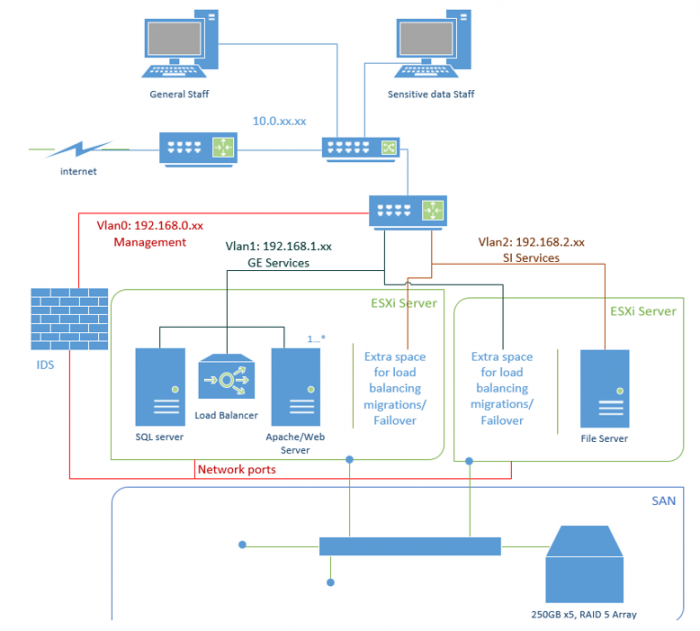
Figure 1 Proposed Topology of Datacentre
Network Topology
Topographically, the datacentre exists attached to the central network of the administration with a router. This location allows the datacentre to communicate with it’s users with the lowest latency possible.
Access to patch the servers directly is provided by the management VLan.
Rack Cabinet
The standard width telephony cabinet would need to be a minimum of fourteen standard units in height to hold the equipment specified.
The rack uses a top-of-rack routing design for network connection, as it is assumed that the facilities for underfloor routing and further aggregation do not exist.
In this scenario, the facilities for end-of-row routing are also unneeded. Mainly due to the small size of the datacentre required, and the redundancy of an additional rack for routing.
In future, when expanding, end-of-row routing would be the preferred option.
Electrically the rack will require dedicated lines to ensure that adequate amperage can be supplied. An uninterrupted power supply will be used as an intermediary to power the rack. This will allow the servers, and other potentially sensitive operations to shutdown gracefully upon power loss. These servers are assumed to not require power during power cuts, as the employees will not be able to work during these times.
Tier
This datacentre is a type two. It implements redundant hardware to improve availability and ensure uptime. But does not provide the multiple cooling, power paths necessary for Tier three. This design does however implement redundant components, a server is able to fail and functionality migrated to restore service. Which puts this design on track for tier three, with future expansion and improvement.
References
Paris, j.-F. & Long, D. D., 2006. Using
Device Diversity to Protect Data against Batch-Correlated Disk Failures. [Online]
Available at: ftp://ftp.soe.ucsc.edu/pub/darrell/StorageSS-Paris-submitted-06.pdf
The Office for
Disability Issues, n.d. Disability prevalence estimates 2011/12. [Online]
Available at: https://assets.publishing.service.gov.uk/government/uploads/system/uploads/attachment_data/file/321594/disability-prevalence.pdf